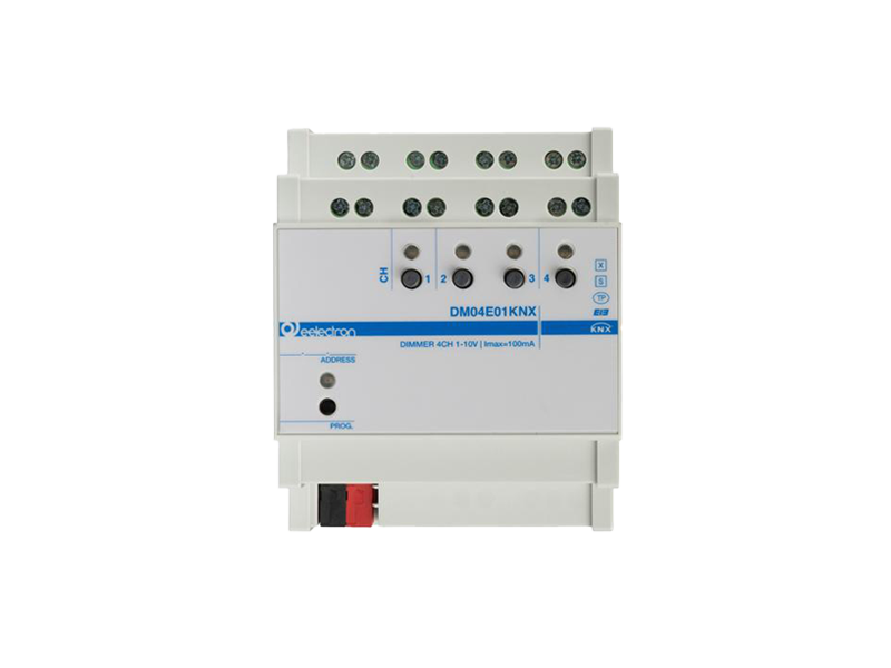
DM04E01KNX is a 4-channel KNX dimmer for the management of electronic ballasts controllable via 1-10 V signal. The device is configurable through the ETS® application.
Technical Data
The device, which does not require additional power supply, also offers the following features:
• Capability to control devices in the following configurations:
• Single channel
• Tunable white (channels 1/3 = cold output – channels 2/4 = warm output)
• RGB
• RGBW
• 4 independent relay contacts, each rated for 16 A, for controlling the power of electronic ballasts
• Flexible relay configuration in relation to the 1-10 V outputs, e.g., for controlling RGBW lamps (1 relay + 4 associated 1-10 V outputs)
• Capacitive load control, meaning no inrush currents
• Operation of switching outputs as actuator/blind control
• Start-up function for fluorescent lamps
• Ability to set channel behavior upon power-up and during dimming
• Timed functions: activation/deactivation delay, staircase lighting function with warning feature
• Possibility to enable: scenes, sequences, blocking, and logic functions
• Energy-saving mode (Economical Mode)
• Dimming characteristic curve customization (up to 5 points)
• 4 manual buttons for controlling the 1-10 V outputs with corresponding LEDs to indicate the channel status
The device features 16 logic blocks that can be used to create simple expressions with logical or threshold operators, as well as more complex expressions with conditional algebraic operators. It also allows the use of predefined algorithms, such as proportional controls for temperature and humidity or dew point calculation. The KNX® communication interface is included.
Mounting & Compatibility
The device can communicate with the KNX® Data Secure protocol and is intended for installation on DIN rail in electrical distribution cabinets and in vertical position with the bus connector on the bottom side as shown in figure 3; it is recommended to ensure adequate dissipation conditions in free air.